Such a question has long been addressed in the context of inverse scattering problems, and a technique has been known that can detect a 2-D periodic grating structure hidden by a diffuser. Recently a technique of ultrafast time-of-flight 3-D imaging that can look around the corner using diffusely reflected light was demonstrated. Also SLMbased technique that compensates the random phase and permit imaging a 3-D object through a diffuser have been reported. The applications of such technique ranges from medical imaging through turbid medium or cell to rescue operations in hazardous condition.
We propose two different techniques for the imaging of 3D object obscured by a diffuser or hidden around a corner. We interpret that the obscuration of the object image is due to the loss of phase information caused by the scattering due to the diffuser. Then we note that the clue to the solution is to find an imaging technique that can cope with the loss of phase information. Indeed, holography is the technique that can recover phase information that is lost by intensity recording in conventional photography. Intensity correlation is another way to reconstruct the object as the mutual intensity of the diffracted field. The reconstruction scheme of the Intensity correlation involves the fourth order correlation of the optical field.
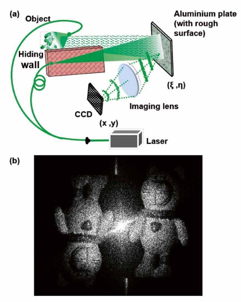
Though our approach based on holography is functionally more restrictive than time-of-flight 3-D imaging, but is much simpler and requires no special equipment such as a femtosecond laser and a high-speed streak camera. We use a reference beam for holography, just as a reference point source used for the SLM-based random phase compensation. Our techniques can be realized easily by the combination of a common CW laser and a conventional camera and does not even require a SLM and the iterative search of the phase distribution that compensates the random phase introduced by the diffuser. The schematic diagram of the setup and the reconstructed object through a scatterer are shown in fig. 1(a) and (b) respectively.
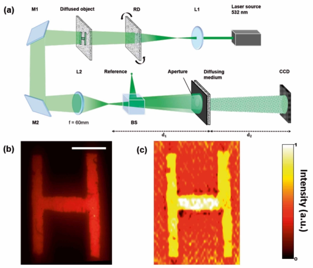
We proposed another technique which is based on intensity correlation for imaging through the diffusing medium and around the corner. The schematic diagram of the setup is shown in fig. 2(a). The object and the reference point source are kept in the same plane in front of the diffuser in a way that they satisfy the condition of isoplanatism, which states that the light from two point sources, lying within the range of memory effect, after propagating through a diffusing media will produce shifted but correlated speckle patterns. Thus the light from the object and the reference produce similar speckle patterns. The image sensor which is kept on the other side of the diffuser records the scattered light as speckle pattern. To reconstruct the object we performed the averaging operation over the speckle pattern by using spatial averaging by means of auto correlation of the intensity distribution. Thus the proposed technique is a single shot, Lensless and real-time imaging technique. By virtue of limited depth of field optical sectioning and the 3D reconstruction is also possible.
Supported by: Alexander von Humboldt foundation for D. Naik and M. Takeda
References:
[1] Singh, A. K.; Naik, D. N.; Pedrini, G.; Takeda, M.; Osten, W.
”Looking through a diffuser and around an opaque surface”, Opt. Exp, 22, 7694-7701 (2014).
[2] Osten, W.; Faridian, A.; Gao, P.; Körner, K.; Naik, D. N.; Pedrini, G.; Singh, A. K.; Takeda, M.; Wilke, M. ”Recent advances in digital holography”, Applied Optics 53 (2014) pp G44-G63.