These surfaces offer additional degrees of freedom to the optical design, allowing to improve the optical imaging as well as to reduce the number of surfaces needed for an optical design. However the fabrication and testing of such surfaces is still a difficult task. At the ITO we developed and patented the so called Tilted Wave Interferometer [1-7] (TWI) which makes it possible to measure these kinds of surfaces. The TWI is a non-null, full-field interferometric measuring technique for aspheric and free-form surfaces with a new degree of flexibility. The interferometer uses a set of tilted wavefronts to locally compensate the deviation of the surface under test from its spherical form. Since it is a non-null technique, there is no need for costly compensation optics. The measurement data acquisition is highly parallelized, leading to a short measurement time in the region of few seconds, by simultaneously achieving a high lateral resolution. The unique combination of these characteristics makes the TWI a perfect candidate for the integration into the process chain of aspheric and free-form surface manufacturing.
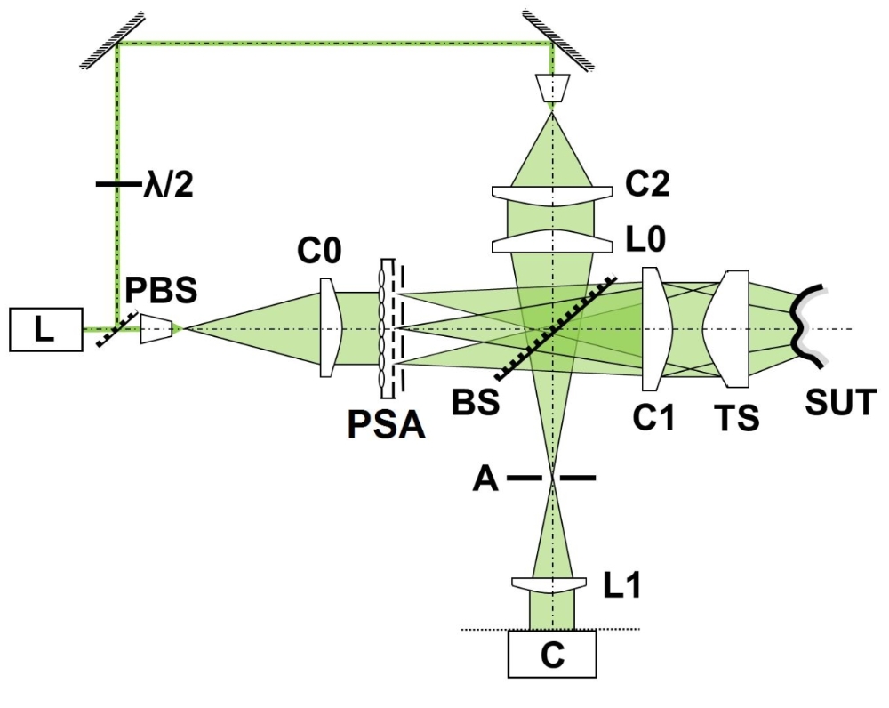
In figure 1 the basic setup of the Tilted-Wave-Interferometer is shown. A coherent laser source L is divided into test and a reference wave by a polarizing beam splitter PBS. The light in the test wave is used to illuminate a micro lens array that is followed by a pinhole array. These two parts serve as an array of point sources PSA for the test wavefronts. The spherical wavefront from each point source is, after passing the beam splitter BS, collimated by C1 resulting in a set of plane wavefronts with different amounts of tilt. The tilted wavefronts are transformed to spherical wavefronts by the transmission sphere TS to compensate the basic spherical form of the SUT. In the case of surfaces with a best fit sphere of infinite radius no transmission sphere is needed. After being reflected by the SUT the wavefronts propagate back to the beam splitter, where they are reflected to the camera arm of the interferometer. In the Fourier plane an aperture stop is located, to block all light that would generate fringes with a density that violates the Nyquist criterion. After the aperture the light passes an imaging optics L1 and interferes with the reference wavefront on the camera C. The distance between the sources in the array is chosen to cover the whole SUT without gaps and a slight overlap. To avoid interference between neighboring sources the measurement is divided into four steps, with only every fourth source enabled in each step. The switching between the sources is realized by a simple aperture array that is moved in front of the micro lenses and blocks every second source in each row and column. As a result phase maps as can be seen in figure 2 are obtained. The main difference of this approach to the scanning type interferometers mentioned above is that the acquisition of the data is highly parallelized, since all test wavefronts are applied to the surface in only four steps. Further, the SUT does not have to be moved during the measurement process. Both these advantages lead to a very short measurement time of far under a minute.
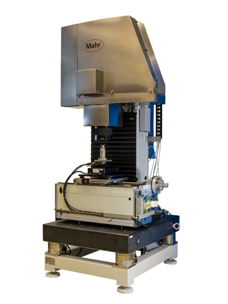
In the BMBF Project Mesofrei, (FKZN 13N10854) a Prototype of the TWI was developed by the company Mahr GmbH in cooperation with ITO.
We further thank EURAMETfor the jointly funding of the EMRP by the EMRP participating countries within EURAMET and the European Union, as well as the Stiftung Baden-Württemberg (Project NanoForm)
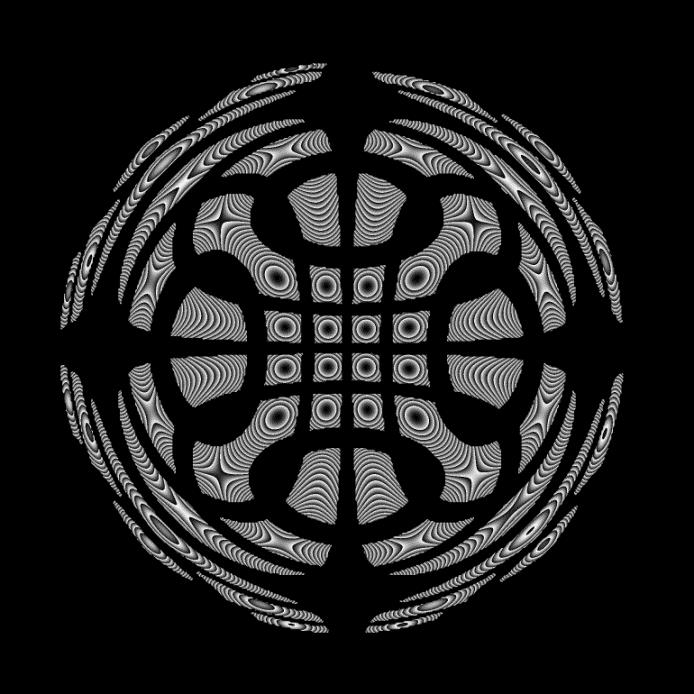
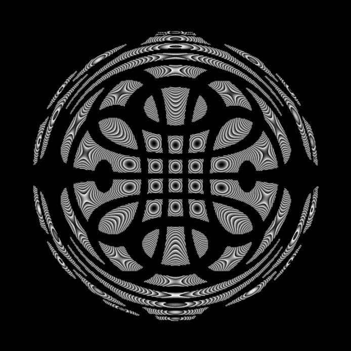
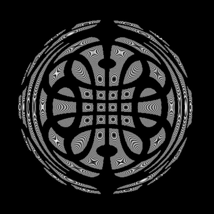
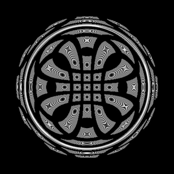
Figure 2: Modulo 2π phase maps as obtained in a measurement of the TWI when measuring an aspheric surface (The wavelength for the calculation of the phase maps was increased for better visualization by a factor of 10)
In figure 4 the measurement result of the aspheric surface shown in figure 3, as well as comparison measurement obtained by a tactile UA3P precision coordinate measurement machine are plotted. The aspheric surface has a clear aperture of 40mm and a deviation from the best fit sphere of 800µm and a slope deviation of up to 5°. The measurement time of the TWI measurement is under one minute, while that of the UA3P was about 40 minutes.
Figure 3: Example aspheric surface with clear aperture of 40mm and 800µm / 5° deviation of the best fit sphere
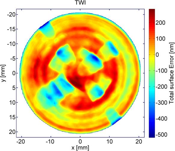
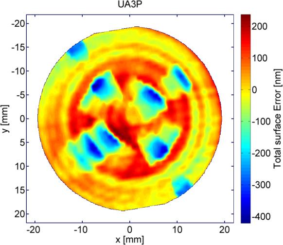
Figure 4: Measurement of aspheric surface obtained by TWI (left) and comparison measurement obtained by UA3P CMM (right)
In figure 6 the measurement result of a diamond turned freeform surface (see figure 5) is shown. The surface has a strong astigmatic shape of about 1mm deviation from the spherical form. The marks from the diamond turning tool are clearly visible in the measurement.
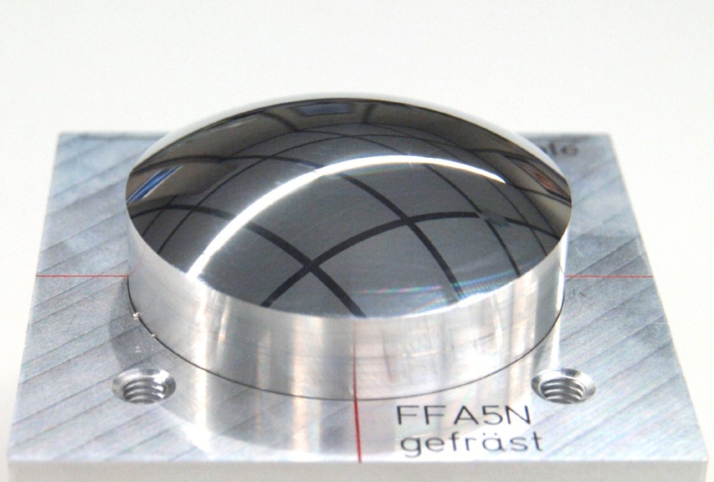
Figure 5: Diamond turned freefrom surface with 1mm of astigmatism
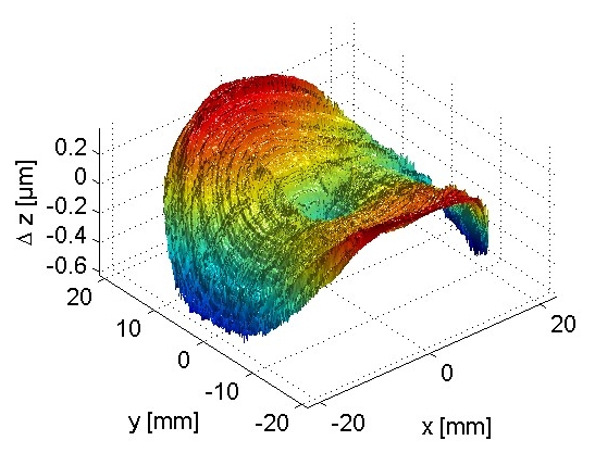
Figure 6: Measurement of diamond turned free-form surface with diamond turning marks clearly visible in the measurement
References
- E. Garbusi, C. Pruss, and W. Osten, “Interferometer for precise and flexible asphere testing”, Optical Letters, Dec. 15, 2008 / Vol. 33, No. 24
- J. Liesener, E. Garbusi, C. Pruss, and W. Osten, “Verfahren und Messvorrichtung zur Vermessung einer optisch glatten Oberflaeche,” Deutsches Patent und Markenamt, 10 2006 057 606.3 (2006)
- E. Garbusi and W. Osten, “Perturbation methods in optics: application to the interferometric measurement of surfaces,” J. Opt. Soc. Am. A 26, 2538–2549 (2009)
- G. Baer, J. Schindler, C. Pruss, J. Siepmann and W. Osten. “Calibration of a non-null test interferometer for the measurement of aspheres and free-form surfaces” Optics Express, Vol. 22, Issue 25, pp. 31200-31211 (2014) http://dx.doi.org/10.1364/OE.22.031200
- G. Baer, J. Schindler, J. Siepmann, C. Pruss, W. Osten, and M. Schulz, “Measurement of aspheres and free-form surfaces in a non-null test interferometer: reconstruction of high-frequency errors,” Proc. SPIE 8788, 878818 (2013).
- G. Baer, G. Garbusi, E. Lyda, W. and Osten, W. 2010 “Automated surface positioning for a non-null test interferometer” OE 49(9), 095602
- G. Baer, J. Schindler, C. Pruss, and W. Osten. 2013. “Correction of misalignment introduced aberration in non-null test measurements of free-form surfaces” JEOS Vol 8 130874 http://www.jeos.org/index.php/jeos_rp/article/view/13074