Deformation can be attributed to the change in the shape of an object in presence of load, heat, gravity etc. The measurement of deformation at micro and macro level is equally important for various applications. Many techniques have been proposed for the same in past but NDT techniques have an edge over others mechanical techniques, and are applicable for measuring the nanometric changes in the surface. Also, the nondestructive measurement techniques are applicable to biological samples, which could be useful for bio-medical studies. The deformation in a surface can be divided into two components (1) in-plane and (2) out of plane. For years Holography is providing a fitting solution for measuring the out-of-plane deformation by calculating the phase difference but measuring in-plane deformation is another challenge. Interferometric techniques were proposed to measure the same, based on multidimensional measurements. Such methods either need multiple references which makes the setup quite complicated or required to record multiple holograms in a sequential way from different directions. Such methods could make the measurements
quite slow and are prone to errors.
The change in phase due to the change in path length is an inherent property of holography, which makes the out-of-plane deformations measurement quite easy and can be done using a single illumination beam. The
intensity information in such experiments are usually a waste product. We propose a setup using single illumination beam to measure full-field deformation. For such measurement system we will utilize the phase as well as intensity information. The schematic diagram is shown in fig. 1. The holographic interferometric technique is employed for measuring the out of plane movements and the in-plane deformation are measured using the correlation of intensity distribution before and after the deformation. The proposed setup can be used for sub nano-metric deformation measurements.
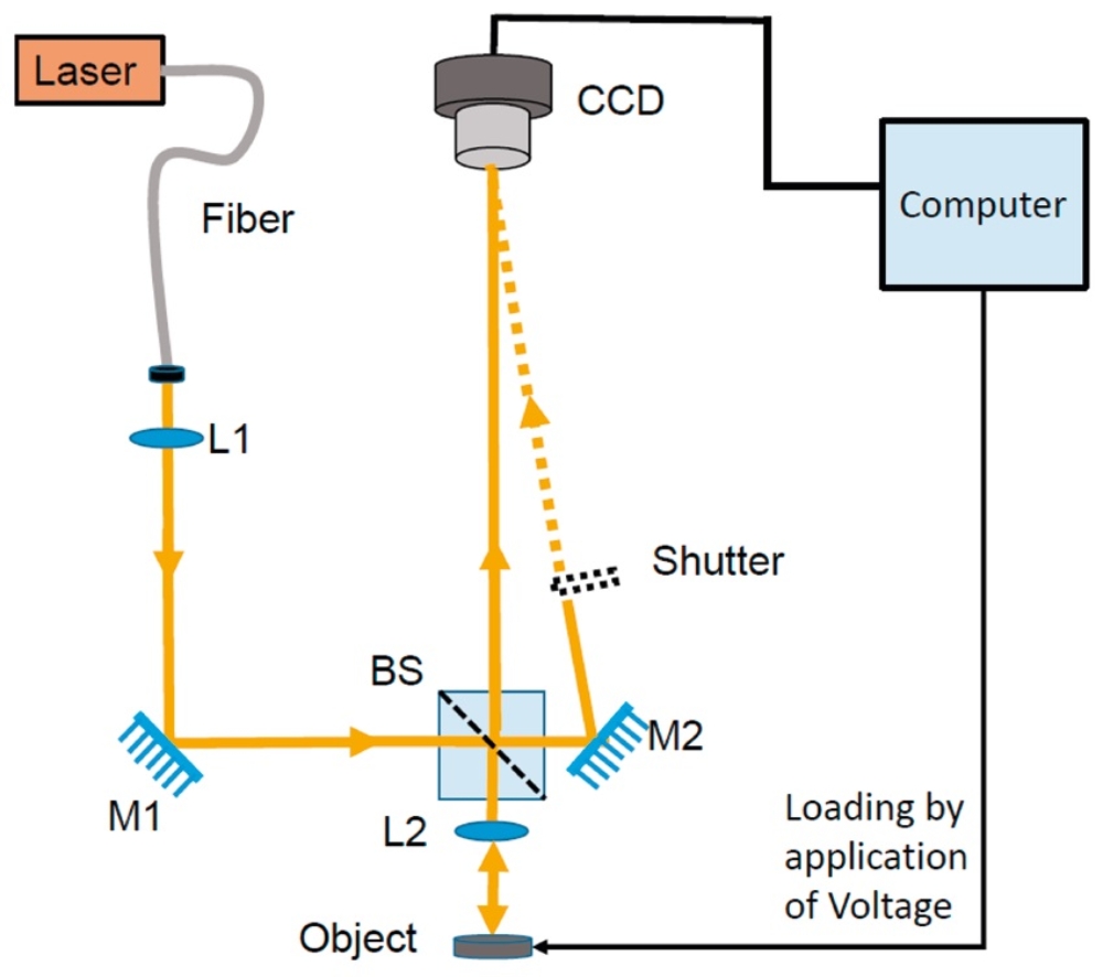
An off-axis holographic setup was arranged and a He-Ne laser was used for illumination. The beam outgoing from the laser is coupled into a single mode fibre and the output beam is collected by the lens L1 and further reflected by the mirror M1 towards the beam splitter BS, which splits the incoming beam into two parts, the reflected beam passes through the lens L2 (f=4.7 mm ) and illuminates the sample. In order to illuminate the sample with a parallel beam, the lens L1 is adjusted to produce a converging beam focusing in the back focal plane of L2. The light reflected by the sample is collected again by L2 which images the sample surface on the CCD sensor with a magnification of 48x. A reference beam obtained from the light transmitted by the BS is superimposed on the beam scattered by the object surface. There is an angle of few degrees between these two waves and thus their interference forms an off-axis hologram, which is recorded by the CCD. The image sensor used in the setup was a PCO Pixelfly with dynamic
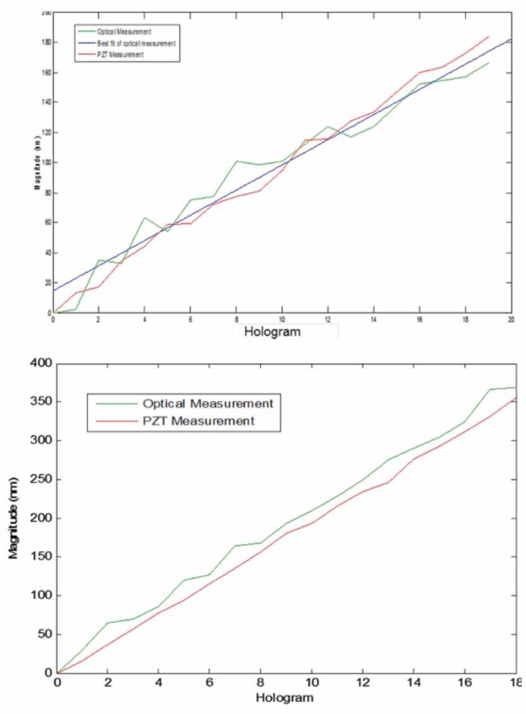
range 12 bit, 1392×1024 pixels and pixel size 6.45×6.45 μm². A shutter was inserted in the setup to block the reference wave, the setup without reference was used to obtain the in-plane deformation. The setup was calibrated using a PZT nano positioner system from Physik Instrumente, with a resolution of 2 nm and a repeatability <10 nm. The setup
can be remotely controlled via internet and was utilized to measure the out-of-plane and in-plane deformations of MEMS structures. The calibration measurements for in-plane and out of plane deformations are shown in fig. 2(a) and (b), respectively.
Supported by: German Science Foundation (DFG)
and the Sino German Center
Project: Remote Laboratory for Optical Micro
Metrology (DFG-OS111/39-1 and GZ 760)
In cooperation with the University of Shenzhen
References
[1] Osten, W.; Faridian, A.; Gao, P.; Körner, K.; Naik, D.; Pedrini, G.; Singh, A. K.; Takeda, M.; Wilke, M., ”Recent advances in digital holography”, Applied Optics 53 (2014) pp G44-G63