The reason for that are differences in the coatings and substrates expansion coefficients, inhomogeneous temperature distribution during the process and the quenching of splats. The mechanical hole drilling technique can be used for the detection of residual stresses in coatings. The residual stresses are locally relieved due to the material removal process, which leads to a deformation of the surface around the hole. These deformations, measured as relaxed strains through strain gauges rosettes, in combination with appropriate calibration data (separately determined by simulation for the layer composite), allows the quantitative determination of the residual stress depth profile. The disadvantage of the strain gauges is that they can only be used on flat and relatively smooth surfaces, where the rosette is applied.
We propose an approach to avoid the mechanical drilling operation and the application of strain gauges, where a pulsed laser is used for the object machining (ablation process) leading to 3D residual deformation by stress relaxation which are measured by an optical system based on digital holographic interferometry. For the validation of the method, test plates were prepared, where aluminium/titan oxide coatings are deposited by atmospheric plasma spraying technique on aluminium substrates.
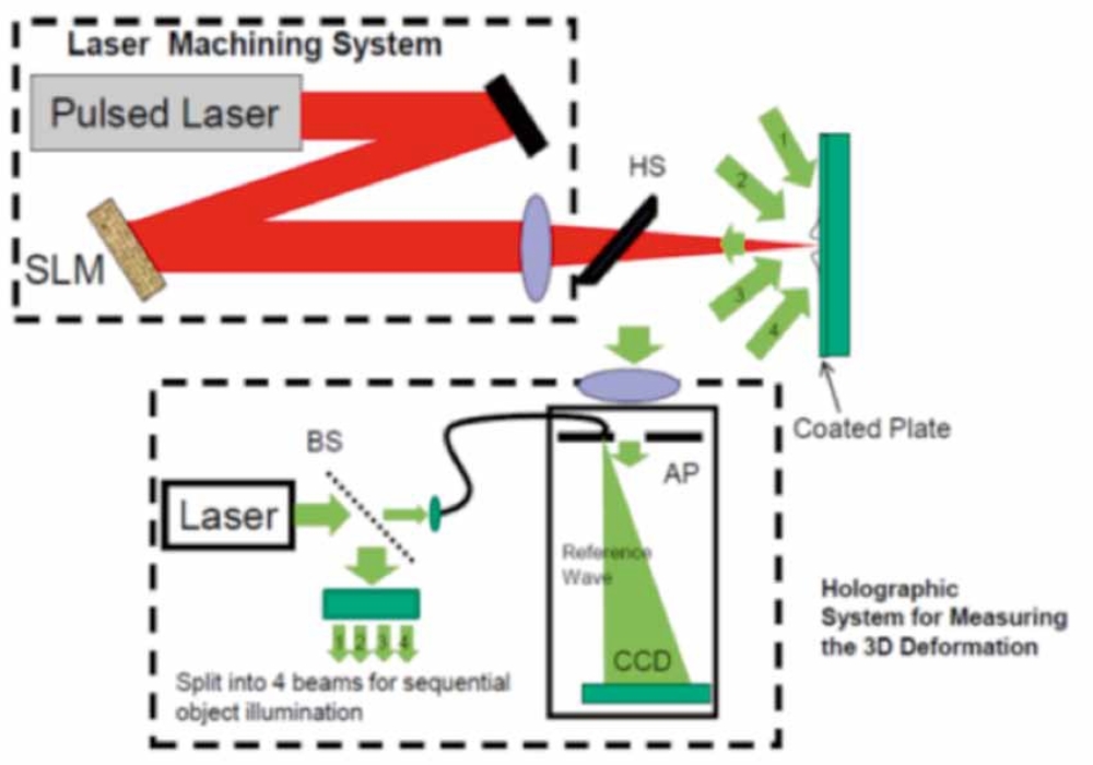
The experimental setup for residual stress analysis (fig. 1) can be divided into two parts one for the machining of the object and the other for the measurement of the resulting 3D deformations. The harmonic separator (HS), transmits the infrared light for the laser machining (wavelength: 1064 nm) andreflects the visible green light (wavelength: 532 nm), for the deformation measurement, allowing at the same time machining and deformation measurements. Laser pulses with a power density higher than 109 W/cm² are used for the ablation of material, in order to obtain such density a laser beam of a few nanoseconds pulse length is focused by a lens on the sample surface. Complex structures are machined by using a spatial light modulator (SLM), where a given light distribution is produced by writing a phase/amplitude pattern (computer generated hologram) on the SLM. The release of residual stresses by the laser machining system produces 3D deformations that are measured by the system based on digital holography shown in the bottom part of fig. 1. Light from a laser is divided into two beams by the beam splitter BS, one is coupled into a single mode optical fibre and serves as the reference beam and the other one is further divided into four beams illuminating the object sequentially from four different directions. The phase of the object scattered wave changes as a function of the deformation and by processing holograms recorded from different illumination directions it is possible to measure the 3D deformation around the machined surface.
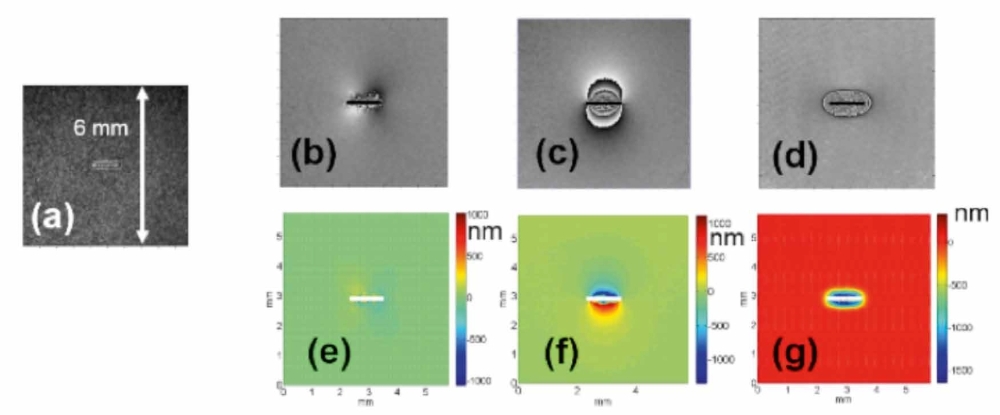
The SLM based system was used for machining structures with different shape and depth on the coated surface. Figure 2.a shows a milled horizontal bar obtained after 64000 laser pulses, the depth of the machined structure is 130 μm. Figures 2. b–g shows the wrapped phase and the corresponding 3D deformations produced by the milling.By incremental loading structures (bars, crosses, rings) having different depth are produced and the resulting 3D deformations are measured. The residual stresses at different depth of the coating are calculated from the deformations together with the profile (shape, depth) of the machined surface and the material parameters. The coating used for the investigations shown in fig. 2 had a thickness of 70 μm, at this depth the residual stress was –250 MPa.
upported by: DFG German Science Foundation
Project: Ermittlung von Eigenspannungen in
beschichteten Oberflächen (OS 111/37-1)
In cooperation with: ”Institut für Fertigungstechnologie
Keramischer Bauteile” and ”Institut für Materialprüfung,
Werkstoffkunde und Festigkeitslehre”.
References:
[1] Pedrini, G.; Martínez-García, V.; Weidmann, P.; Wenzelburger, M.;Killinger, A.; Weber, U.; Schmauder, S.; Gadow, R.; Osten, W.
”Residual stress analysis of ceramic coating by laser ablation and digital holography”, submitted for publication in ”Experimental Mechanics”.