Optical incremental rotary encoder in low cost design
Rotary encoders are used for angular measurements in numerous applications like rotating machine parts, electrical motors or for example to detect the steering angle in cars. There are different encoding principles available such as potentiometric, capacitive, inductive or optical, with the optical systems reaching the highest angular accuracy. As a disadvantage the resolution enhancement of optical encoder systems up to now is associated with increasing cost.
Cost effective: diffractive solid measure on a plastic disc
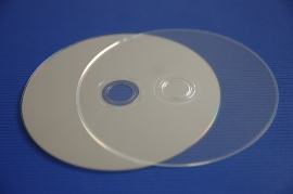
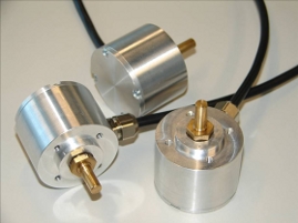
Considering the need for competitive sensors, we have developed a new concept for low cost optical rotary encoders. The basic idea is to use a micro patterned plastic disc with a metal coating, as it is used for a Compact Disc or DVD. This encoder disc can be manufactured by a conventional DVD injection compression moulding process. With this well known technique it is possible to create highly precise micro patterns while running a cost effective process for high numbers of parts.
The mechanical and electronic design and the realization of this new kind of optical rotary encoders was performed by our project partner, HSG-IMAT. We focused on the optical design as well as the fabrication of the testmaster discs.
The testmasters were directly written into photo resist on the circular laser writing system CLWS 300M.
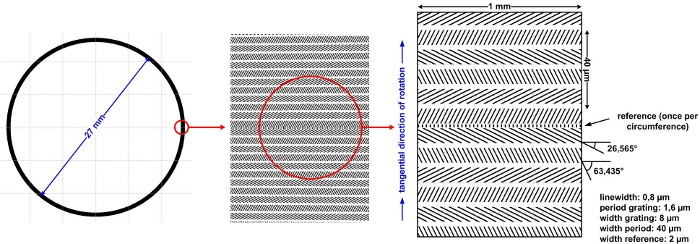
Fig. 1: diffractive solid measure
The solid measure consists of a micro pattern of diffracting gratings placed in a circle on the outer radius of the encoder disc. An incremental code is generated by a periodic arrangement of patterned and unpatterned fields, which diffract the incident coherent beam into different diffraction orders.
Diffractive sensor principle
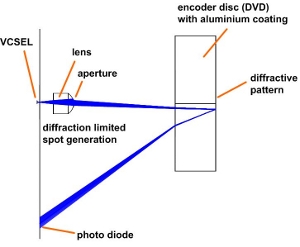
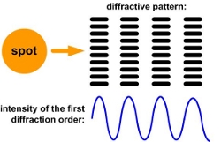
Fig. 2: Generation of a sinusoidal signal
Having an alternating pattern of fields without and with a diffractive grating, the intensity of the first diffraction order of the reflected beam results in a sinusoidal signal, which can be detected by a photo diode. A sinusoidal signal is the desired signal for most applications.
Offset compensation & detection of rotation direction
To not only achieve an incremental measurement but also a detection of the rotation direction, it is necessary to implement a second incremental track that is 90° phase shifted towards the first. The usage of a different grating leads to a second set of diffraction orders where again the first order is detected by a photo diode. To obtain an offset compensated output signal this setup is used twice in a nested configuration having four different gratings per period.
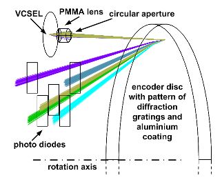
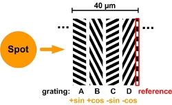
Fig. 3: Generation of four sinusoidal signals & reference by spatial separation
The spatial separation of the resulting four first diffraction order spots is achieved by using different angles for each set of gratings per signal. To meet the common request for a reference mark, a fifth grating is implemented to mark the zero position once on the circumference. This generates a reference signal on a fifth photo diode.
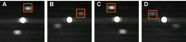
Fig. 4: Signal detection from first order spots on four photodiodes
Alignement-free sensor assembly
The dimensions of the patterns of the gratings and therefore the angular resolution of the encoder depend directly on the illumination spot size and the geometry. In turn this defines the fabrication tolerances of the system. To cope with the mechanical tolerances, the optical components of the sensor are assembled on a MID (Moulded interconnect Device). The photo diodes and the light source are directly bonded onto the MID. The assembly of the polymer lens and aperture is done without any alignment procedure.
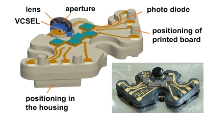
Fig. 5: MID optic module
In the current concept a disc of 27 mm diameter is chosen to fit into a housing with about 37 mm outer diameter. With an incremental tangential period of 40 µm the hardware resolution results in 2048 periods per revolution, what can be easily interpolated electronically with a standard circuit in order to obtain a higher resolution output if necessary.The MID optic module is attached to an integrated printed board where the signal processing is performed.
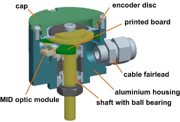
Fig. 6: Assembled sensor
References
- D. Hopp, CH. Pruss, W. Osten, J. Seybold, V. Mayer, H. Kück: Optischer inkrementaler Drehgeber in Low-Cost-Bauweise, tm - Technisches Messen, Jahrgang 77 (2010) Heft 6 S.358-363, Oldenbourg Verlag, 2010, München
- D. Hopp, Ch. Pruss, W. Osten, J. Seybold, V. Mayer, H. Kück: Optical incremental rotary encoder in low cost design, Sensor & Test Conference Proceedings Opto 2009, 3.4, Nürnberg
- Hopp, D.; Pruss, Ch.; Osten, W., Seybold, J., Mayer, V., Kück, H.: Untersuchungen zu einem hochauflösenden optischen Drehwinkelsensor in Low-Cost-Bauweise; Projektabschlussbericht, AiF ZN219, Universität Stuttgart, Stuttgart 2008
- Hopp, D.; Pruss, Ch.; Osten, W., Seybold, J., Mayer, V., Kück, H.: Hochauflösender optischer Drehgeber in Low-Cost-Bauweise; DGaO-proceeding, Esslingen, 2008.
- Seybold, J., Mayer, V., Kück, Hopp, D.; Pruss, Ch.; Osten, W.: Hochauflösender optischer Drehgeber mit MID-Optikmodul; 6. Paderborner Workshop "Entwurf mechatronischer Systeme", Paderborn 2009
- Mayer, V.: A new concept for an absolutely encoded angular resolver; Presentation on 4M 2007 Conference on Multi-Material Micro Manufacture, Borovets, Bulgaria, 2007
- Alexander G. Poleshchuk, Evgeny G. Churin, Voldemar P. Koronkevich, Victor P. Korolkov, Andrei A. Kharissov, Vadim V. Cherkashin, Valerii P. Kiryanov, Aleksei V. Kiryanov, Sergei A. Kokarev, and Alexander G. Verhoglyad: Polar Coordinate Laser Pattern Generator for Fabrication of Diffractive Optical Elements With Arbitrary Structure; Appl. Opt. 38, 1295-1301 (1999)