Rotary sensors are used in numerous manufacturing and automotive applications, where cost effectiveness is a major criterion. To meet the increasing demand for competitive optical rotary encoders a micro-structured plastic disc, manufactured by a conventional and cost-effective DVD-moulding Process, can be used to replace the common but costly glass disc [1].
In a previous AiF-project (219 ZN) a new kind of incremental encoder was presented [2, 3], where the realisation of the mechanical and electronical design were performed by our project partner, HSG-IMAT, while the optical layout and the design of the new diffractive incremental code were performed by ITO [4].
Consisting of four different binary phase gratings with a periodic sequence and being illuminated with a Gaussian spot, the grating structure generates a sine- and cosine-signal by detecting the first order spot intensities of its diffraction pattern. The four gratings have different orientation angles to separate the diffracted spots. With that principle, on a diameter of 27 mm a resolution of 2048 solid measure increments on the circumference can be achieved. By interpolation of the signals this leads to up to 15 bit of incremental steps.
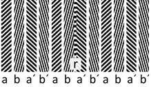
Fig. 1: Detail of the incremental diffractive solid measure
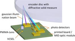
Fig. 2: Scheme of the diffractive incremental encoder setup
For some applications, e.g. robotics, it is essential to also know the absolute angular position. For this purpose, the diffractive code was enhanced by exploiting a residual degree of freedom: By variation of the gratings periods and angles the resulting first order spots on the detector plane can be moved arbitrarily. To obtain an absolute coding, ten different positions of a single first order spot are used to encode ten different states. The spot positions can be determined by detecting the intensitie’s centre of gravity on an array of photodiodes or a position-sensitive device.
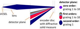
Fig. 3: By a variation of the grating period the diffraction angle of the first order spot can be controlled to hit ten different positions in the detector plane
Again, the solid measure consists of four spatially separated gratings, each of those having ten states which vary periodically from the largest to the smallest grating period and back. A continuous variation is necessary since jumping between the minimum and maximum spot position would lead to an ambivalent state for the associated angular position signal.
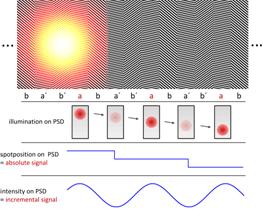
Fig. 4: Generation of a combined incremental and absolute signal using a variation of the grating period and angle to modify the diffraction angle and therewith the position of the first order spots on the detector plane
To build the absolute code, the signal from the first set of gratings, respectively on the first detector, covers the whole circumference with two steps, dividing it into twice 180 degrees. The second set of gratings on the second detector has twenty steps per circumference, dividing each step of the first into ten steps. The angular segmentation now is coded in 20 explicit states.
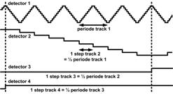
Fig. 5: Schematic illustration of the absolute coding with four nested tracks. Each track provides ten different states which vary periodically. By cascading the four signals, an absolute Gray code with 2000 explicit states is built.
Each of those 20 steps generated by the two first signals is subdivided ten times by the third signal, whose period thereby is ten times shorter, which leads to 200 angular segments. The fourth set of gratings again generates a signal with a tenth of the period length of the previous set and therewith contains the highest resolution of the cascaded code. The number of absolute states results in 2000, respectively in 2000 angular segments. which corresponds to 10.8 arc-minutes each. The absolute code therewith provides a resolution of 10.9 bit generated in the Gray code principle.
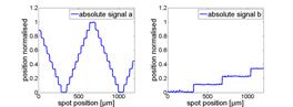
Fig. 6: Experimental results for the two first of the four absolute signals.
Compared to a common binary Gray code, with the presented absolute code the challenge of the correct switching point doesn't need to be handled, because the detection of the centre of intensity can be done step-less. Furthermore, the principle only needs a single diffractive track as a solid measure, which makes it very robust to a radial shift of the encoder disc.
While the position of the first order spots is used to generate the absolute signal, the varying intensity of the spots still is used to generate the known incremental signals. With 2000 periods, the incremental code physically corresponds to the absolute code, the two principles do not affect each other. Therewith, each period of the interpolated incremental signal can be explicitly identified by using the absolute code. The absolute resolution of the combined principles results in 15 Bit or even higher, depending on the accuracy of the interpolation.
Supported by: AiF (349 ZN)
Project: “Untersuchungen zu kostengünstigen absolut und inkremental kodierten optischen Drehgebern mit justagefreier Endmontage und mikrostrukturierter diffraktiver Maßverkörperung aus Kunststoff”
References
- Mayer, V., "Untersuchungen zu optischen Drehgebern mit mikrostrukturierten Maßverkörperungen aus Kunststoff", Institut für Zeitmesstechnik, Fein- und Mikrotechnik, Universität Stuttgart (2009).
- Hopp, D., Pruss, C., Osten, W., Seybold, J., Mayer, V., and Kück, H., "Optical incremental rotary encoder in low cost design", in Sensor &Test Proceedings Opto 2009 (2009).
- Hopp, D., Pruss, C., Osten, W., Seybold, J., Mayer, V., and Kück, H., "Optischer inkrementaler Drehgeber in Low-Cost-Bauweise", Technisches Messen 77, 358-363 (2010).
- Poleshchuk, A., Churin, E., and Koronkevich, V., et. al., "Polar coordinate laser pattern generator for fabrication of diffractive optical elements with arbitrary structure", Applied Optics 38, 1295-1300 (1999)