Abstract
Besides the many advantages minimally invasive surgery offers, the surgeon suffers from the loss of information, visual and mechanical (haptic feedback). The latter of the two can help to localise tissue abnormalities (benign vs. malign tissue). We are aiming to generate a reliable constitutive FE model of the organ describing its mechanical properties by employing multiple elastographic measurement techniques at different scales (cell, tissue, and organ). Besides measurements on biological samples, a silicon phantom has been generated for the purpose of testing the transfer of information (delivery and processing of data). The stress-strain curve was recorded and embedded in the FE Model (Arruda-Boyce). A 2D displacement map was experimentally obtained from the phantom, which was in good agreement with the FE simulation.
Introduction
Minimally invasive surgery has for many applications replaced the open surgery, since the amount of tissue, which has to be cut, is reduced, resulting in a quicker recovery of the patient connected with reduced post operational stress. Moreover, it offers some aesthetical advantages such as for facial operations. Besides all these advantages, minimal invasive surgery has restricted the working environment of the surgeon due to the loss of two mayor human senses, three dimensional vision and haptic feedback. The haptic feedback is an important tool, which is used in open surgery for tumour localisation due to its increased stiffness compared to healthy tissue (palpation). The elastic modulus of the tumour is 7-14 times higher than for healthy tissue. Our vision is to assist the surgeon during minimally invasive surgery by re-establishing the sense of touch, albeit with an increased sensitivity, increased lateral resolution and the new feature of in depth localisation.
Principle
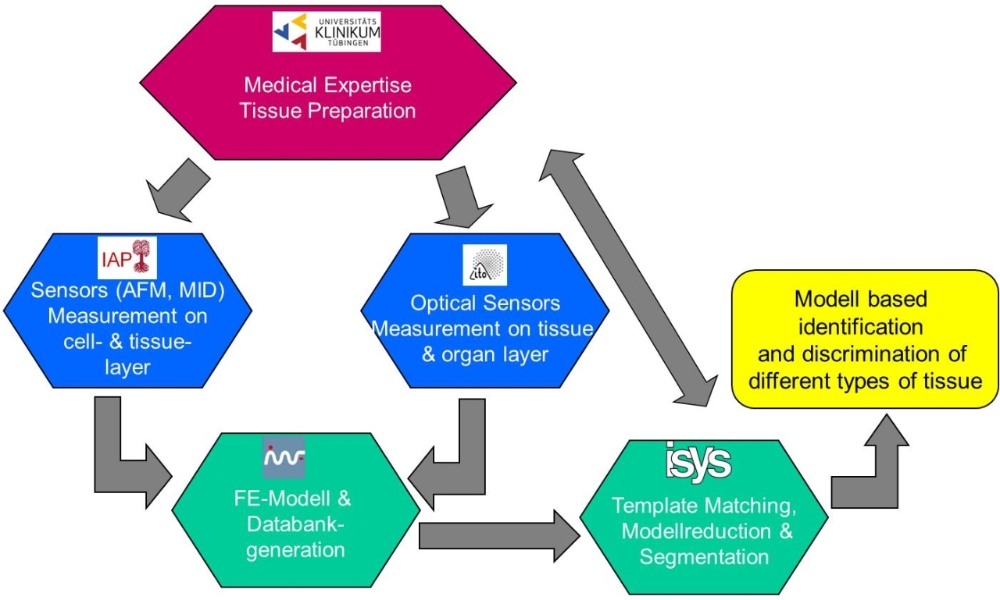
The measurement principle to obtain information about the mechanical properties is called elastography. The working principle is based on the comparison of at least two different states of the tissue (unloaded and loaded), while an external force is applied to it. Due to its increased stiffness, tumours tissue deforms less than healthy soft tissue. By comparison of the two data sets the elastic properties of the tissue can be obtained and tissue abnormalities can be localised. In that manner small tumours and/or enlarged lymph nodes hidden underneath the peritoneum, which may not have been registered in the pre-operational data, can be found. Measurements are recorded on multiple scales of resolution (cell, tissue, organ) employing multiple elastographic techniques (e.g. AFM, 2D image correlation). Results are fed into a Finite Element (FE) model to generate an accurate description with regards to the elastic behaviour of an organ. A flow diagram highlighting to transfer of information is displayed in Fig. 1.
Result
The project is a multidisciplinary project, combing people of different expertise and background, using different scientific terminologies, different software packages and different equipment. At a first stage it is important to ensure the transfer of information between the different partners e.g. defining common interfaces. Therefore, a silicon phantom has been generated exhibiting similar geometric dimension and elastic properties as a kidney (biological sample of interest). The stress-strain curve was measured using a well-defined cylindrical silicon probe and the transferred to the partner generating the FE-Model. The phantom was then loaded using the ITO manufactured roll indenter, see Fig. 2. In order to track the deformation particle imaging velocimetry has been employed. A deformation vector field could be obtained comparing the location of the particles before and after the application of an external force. A contour plot of the deformation field is displayed in Fig. 2(c), central image. The dimension of the phantom, the coordinates of indentation with respect to the edge of the phantom, and the indenter geometry was transferred to FE modelling partner. The underlying FE- Model to simulate the viscoelastic behaviour of soft tissue was based on the Arruda-Boyce Model, which is commonly applied for the modelling of soft tissue. It offers the advantage of only requiring two parameters, shear modulus and locking stretch. The deformation maps obtained from the experiment and from the FE-Model have been compared. The cross-section plot shown in Fig. 2(c) demonstrates that a good match was obtained for the central position (from 15 to 40 mm).
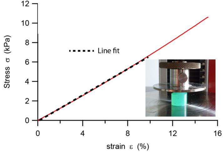
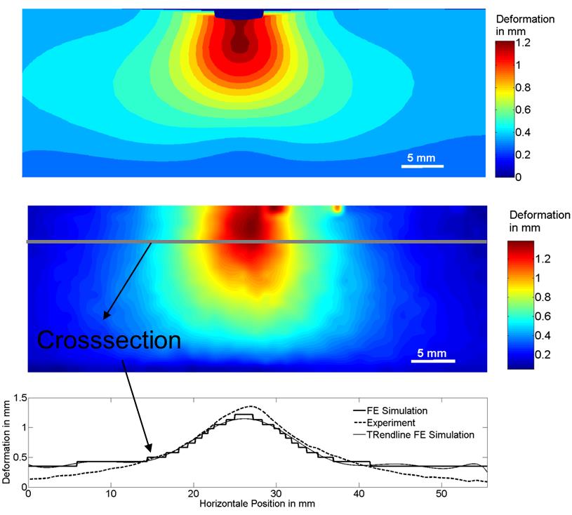
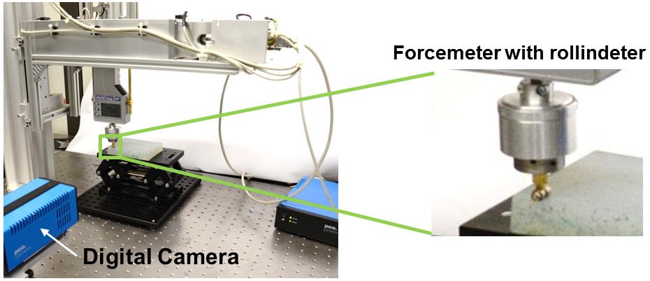
Figure 2: Experimental setups and results (a) stress-strain curve with microindenter and the cylindrical silicon sample displayed on the right side of the diagram, (b) experimental setup for rollindentation and optical imaging system, (b) deformation maps obtained top to bottom: FE-Modell, experimental results, cross-section plot (good match at central position)